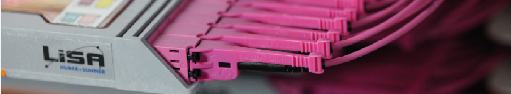
LISA (Leading Inter-connect System Approach)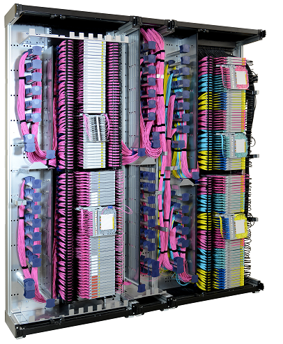
LISA is a dedicated high-density fiber management system commonly used as a centralised cross-connect in the main distribution area (MDA) of large data centers. With a 300 mm depth and full access from the front side, LISA cabinets can be positioned against unused walls, at the end of cold aisles or back-to-back on a single floor tile.
LISA racks have a density of 1500 LC ports per rack or 3000 LC ports per tile when placed back-to-back. For MTP® applications the density is 1080 or 2160 MTP® ports respectively.
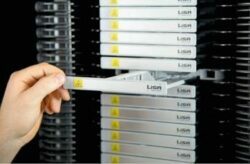
The main difference between LISA and conventional 19″ panels is the fact that LISA is fully accessible from the front side.
This means that users can install, patch or remove fiber trays simply by sliding out the tray. This feature is much more attractive than 19″ panels which generally require access to the rear side of the cabinet.
Patching to the LISA rack is fast and easy and a dedicated slack storage area for jumpers allows users to make “any-to-any” patching with just two lengths of cord.
Modular and scalable
The CDR is the most flexible and scalable fiber management system on the market. Tray units and fiber trays can be used like building blocks to create high-density systems from smaller, more scalable sub-segments.
Different fiber performances, connectivity types and applications can be mixed and matched in the same rack so that the overall solution can evolve at the same pace as the data center.
100 % access from front side
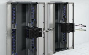
Unlike other fiber management systems on the market, LISA is allows complete access to all incoming and outgoing fibers from the front side. Conventional systems require access to the rear of the cabinet but with LISA everything is “front access”.
This innovative approach allows operators to position the LISA rack back to back on a single floor tile for increased density, or alternatively against an unused wall.
LISA racks can also be placed against the side of equipment cabinets or at the end of cold/hot aisle containment systems.
Simpler moves, adds and changes
The LISA side access system benefits from integrated cable service loops that facilitate “anytime access” to all cables and connectivity. Because of the innovative side-facing design, rear and front connections can be accessed quickly and intuitively without any risk to pre-installed fibers.
The integrated cable management system is easy to follow and allows users to add or remove cables at any time during the life cycle of the product.
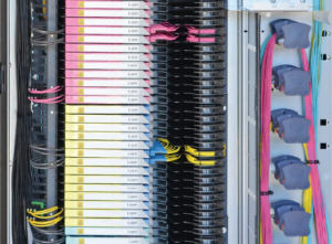
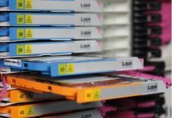
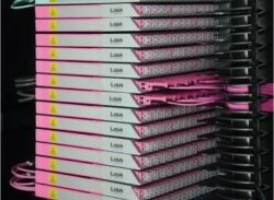
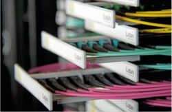
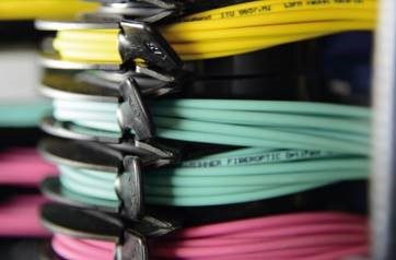
The fiber tray is available in different colours for faster identification and traceability. Our side-facing system makes visibility of the channel faster and more intuitive for the user reducing the operational costs incurred during the life cycle of the data center.
LISA patching solution for Greenfield LC and MTP® installations 10G/40G/100G
A new or refurbished facility is an ideal opportunity to consider the long-term needs of your cabling infrastructure. Cabling is there to support your switching architecture and active devices, so implementing a system which supports future data rates like 40G and 100G is strongly recommended.
The rise in parallel-optics MTP® transceivers means that end-toend pre-terminated cabling systems are often the main cablin system within the data center. Being able to install and patch these new cables quickly and easily is critical from an operational perspective and also a business-ready perspective.
The LISA patching solution is purpose-made for this application and subsequently simplifies the complete process of installing and servicing MTP® cable systems. The LISA patching tray can also be used for LC serial patching as an alternative to pigtail splicing
LISA splicing and MTP®-LC transitions for Greenfield/Brownfield 1G/10G
Brownfield data centers are often faced with the challenging task of maintaining mixed applications and data rates within the same environment. Some operators prefer to deploy singlemode fiber over LC connectivity and others prefer to deploy multimode fiber with a mix of MTP® and LC connectivity.
CDR cable distribution rack and tray units
Highest packing density for evolving data centers
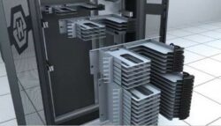
The CDR (Cable Distribution Rack) is a purpose-built high-density fiber management rack which serves as a central cross-connect in the main distribution area of data centers. With a footprint depth of only 300 mm, the CDR is fully modular and scalable up to 1620 ports (3240 fibers) using LC connectivity and 1080 ports (25 920 fibers) using MTP® connectivity. Users can benefit from a C-shaped construction where all internal sub-elements are completely installable and accessible from the front side. This important feature means that CDRs can be placed back-to-back on a single floor tile or alternatively against an unused wall for minimal space consumption.
Configured to suit your needs
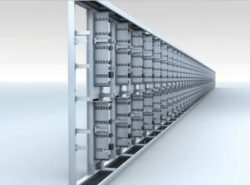
The CDR is 47U high, 300 mm deep and comes in two standard width dimensions of 900 mm and 1200 mm.
The 900 mm version is designed for splicing and MTP®-LC furcation trays and the 1200 mm version is intended for patching only, whether it be LC or MTP® cable systems.
Key features CDR and tray units
C-shaped design for easy patching and improved access.
The “two-post” construction of the LISA CDR dramatically improves the access to connectivity when making moves, adds and changes. CDR racks can be positioned side-by-side, and cables can be routed from one rack to the other without the need to feed jumpers behind vertical posts.
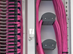
Integrated slack management of jumpers
Managing thousands of fibers in a single rack is virtually impossible without dedicated patch cord management. The LISA rack is supplied with this feature fully integrated from the start so that installers can safely route and manage patch cord slack every time they make a patch. Furthermore, the integrated management reduces the quantity of different length patch cords required to make connections. Only two different length cords are required to connect any of the ports.
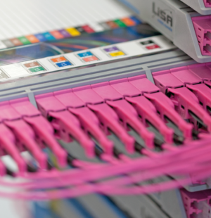
Clear identification and traceability
The second you walk up to a LISA rack you know that a great deal of time and investment has been spent on making this system visible. Fiber trays inside the rack are coloured for immediate identification and clear labelling on the front of the fiber tray allows users to locate connections in seconds. These features help to reduce installation and serving times and have a significant impact on the operational costs of the data center.
LISA side access tray units
- Characteristics
- Integration of MTP® transition fiber trays
- 19″ rear-mounting for improved access to front
- Horizontal fiber tray mounting maximises available height in rack
- Universal fixing plate for 2 conduits (splicing) or 3 MTP® adaptors
- Integral service loop for patch cords
- Horizontal and vertical patch cord guides
- Integrated patch cord mandrels for bend-radius protection
- Patch cord retaining ring ensures safe strain-relief of patch cords exiting the unit
Standard tray units for pigtail splicing and MTP®-LC transition
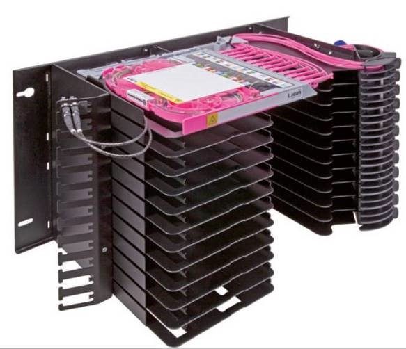
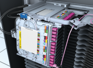
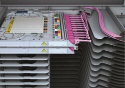
The LISA standard tray unit is a high-density chassis which manages pigtail splicing or MTP®-LC transition fiber trays inside the centralised cross-connect rack. Incoming backbone cables enter the tray unit from the left hand side and jumper cables are connected on the right hand side of the tray unit.
Due to 19″ fixings at the rear of the tray unit, full access can be enjoyed to all incoming and outgoing fibers and the integrated service loops allow the fiber tray to be inserted and retracted quickly and easily.
Standard tray units are supplied in 7U units with a density of 15 fiber trays in total. Fully loaded 47U high CDR racks will accommodate a maximum of 6 7U tray units or 90 fiber trays.
- Key features tray units
100 % accessibility from front side
The LISA tray unit allows incoming cables and outgoing jumpers to be fully installed and serviced from the front side without the need to access the rear of the cabinet. Integrated slack storage areas allow fiber trays to be slid in and out of the tray unit in just a few seconds without disrupting pre-installed fibers.
Mix and match in the same rack
Splicing fiber trays and MTP®-LC transition trays can be mixed together in the same centralised cross-connect rack due to the universal fixing plate on the side of the tray unit. This is a great feature for operators who have pre-installed spliced fibers but want to move to a more flexible MTP® backbone. Multimode and singlemode trays can also be mixed and matched giving even more flexibility and scalability.
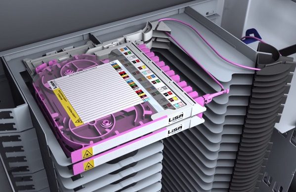
LISA fiber trays
LISA fiber trays are the side-facing connectivity blocks that are inserted into tray units within high-density CDR racks. Designed for speed of installation and improved accessibility, the LISA fiber trays can be installed and removed in under 10 seconds.
Fiber trays are available to cover a wide range of applications including pigtail splicing and MTP®-LC transitions. Within the data center the majority of splicing applications are singlemode LC because this combination provides a future-proofed infrastructure which is low-loss and precise in terms of cable slack management.
MTP®-LC transitions on the other hand are generally multimode OM3 or OM4, allowing the operator to re-use the MTP® backbone and upgrade it later to parallel optics up to 40G and 100G.
In addition to the pigtail splicing and transition fiber trays, HUBER+SUHNER also offers a patching fiber tray which is designed to serve the increasing trend towards MTP® parallel optic applications. The patching tray is also suitable for singlemode LC patching in applications where fast, factory tested links are required.
Key features fiber trays
- 100 % accessibility from front side
 The LISA tray unit allows incoming cables and outgoing jumpers to be fully installed and serviced from the front side without the need to access the rear of the cabinet. Integrated slack storage areas allow fiber trays to be slid in and out of the tray unit in just a few seconds without disrupting pre-installed fibers.
- Mix and match in the same rack
 Splicing fiber trays and MTP®-LC transition trays can be mixed together in the same centralised cross-connect rack due to the universal fixing plate on the side of the tray unit. This is a great feature for operators who have pre-installed spliced fibers but want to move to a more flexible MTP® backbone. Multimode and singlemode trays can also be mixed and matched giving even more flexibility and scalability.
- Installation in under 10 seconds
 The fiber tray can be installed in under 10 seconds without any special tools or training. The integrated sliding feature and self-locking system makes the installation simple, fast and repeatable. This core feature contributes to faster deployment times and tighter project windows.
- Excellent fiber routing with bend-radius protection
 The fiber tray is designed to manage fibers safely and neatly without compromising user-handling or optical performance. The internal guiding elements of the tray maintain the minimum bend-radius of fibers and also provide clear separation between incoming fibers and pre-loaded pigtails. Out-going patch cords are safely guided away from the tray with an integrated guiding arm.
This guiding arm maintains a horizontal guidance of the cables and provides a consistent service loop for regular moves, adds and changes.
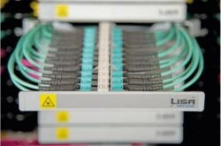
LISA patching tray
 LISA patching trays are generally used to build a cross-connect (system-to-line) configuration either within the same optical distribution rack (ODR) or between adjacent ODRs and servers with highest flexibility when using pre-terminated and factory tested cable systems.
Cable systems can be patched easily thanks to a sliding and pivoting design. Cables enter the patching tray from the rear left and right hand side of the tray unit and are then horizontally managed before entering the patching tray. This unique system differs from other patching trays because the tray is side facing and not forward facing. This means that cables connected to both sides of the LISA patching tray can be accessed simply by sliding out the tray. All cables that enter or exit the LISA patching tray have an integrated service loop so that removal and insertion off the LISA patching tray can be made without having to manage a lot of cables each time a patch is made.
In data centers, the LISA patching tray provides a simple upgrade path from LC based 10G systems to MPO based 40G and 100G systems. This is possible because each LISA patching tray in the patching tray unit can be individually removed and replaced. In other words, LC patch panels can be replaced by MTP® patch panels during the life cycle of the data center.
Key features patching trays
- 100 % accessibility from front side
 The LISA patching tray unit allows incoming cables and outgoing jumpers to be fully installed and serviced from the front side without the need to access the rear of the cabinet. Integrated slack storage areas allow fiber trays to be slid in and out of the tray unit in just a few seconds without disrupting preinstalled fibers.
- Suitable for next generation data rates of 40G and 100G
 Data centers are steadily moving away from LC based serial connectivity to parallel based MTP® connectivity. This evolution requires a new range of distribution products and connectivity methods that offer flexibility and scalability for the future. The patching tray facilitates this evolution path because it manages both incoming and outgoing MTP® trunks and jumper cables. Base-8, 12 and 24 MTP® cable types can be accommodated in LISA patching trays
- Installation time under 10 seconds
 The patching tray can be installed in less than 10 seconds without any special tools or training. The integrated sliding feature and self-locking system makes the installation simple, fast and repeatable. This core feature contributes to faster deployment times and tighter project windows.
- Excellent fiber routing with bend-radius protection
 Every aspect of a professional fiber management system needs to balance the usability of the product with important technical requirements. Bend-radius limitation ensures that the light within a fiber-optic cable travels from one end of the link to the other. Even despite the rise in popularity for bend-optimised cables, safe and clear guiding systems are paramount to a future-proofed system.